Precision Tool Performance
Tipco routinely works with customers and other stakeholders to help identify and implement recommendations aimed at optimizing tool performance (and tool life). For example, Tipco works with customers to identify material, design, and coating that help optimize tool performance. Tipco routinely works with customers and other stakeholders to mitigate and eliminate tool performance issues and concerns that can cause costly production downtime. Collectively, Tipco has over 100+ years of precision tool manufacturing experience.
Common Issues & Solutions
Tool performance is critically important to Tipco customers. Tipco routinely works with customers to help identify tool performance issues and concerns. More specifically, Tipco works with customers to help identify and eliminate tool performance issues (i.e. cracking, bending, breaking). Furthermore, Tipco routinely works with customers to help identify and implement solutions aimed at optimizing tool performance. Collectively, Tipco has over 100+ years of precision tool manufacturing experience. As a result, Tipco has an in-depth understanding and knowledge of tool performance criteria.
Punch durability is largely dependent upon induced stress levels (relative to the ultimate strength of the component material). Due to the nature of applied loads, breakage generally occurs during the perforating process; whereas, most cutting-edge wear develops during stripping. For perforating punches, head breakage is a serious concern. Often times, this concern can be mitigated by increasing the shank diameter so that the load is distributed over a larger area, thereby reducing the stress value.
Improved punch durability can sometimes be achieved by a blend radius that reduces stress concentration in critical areas. For example, cutting edge chipping can be reduced or eliminated by stoning a 0.002” to 0.004” radius or chamfer on the component. This procedure effectively increases the contact area resulting in a lower stress level.
The perforating process subjects punch components to a variety of forces, including the following: compressive tensile forces; frictional forces; and, deflecting forces.
Punch-to-die alignment is an expression of the degree of clearance uniformity between corresponding points on the cutting periphery between a punch and die button. The equation is relatively straightforward: better alignment equals more uniform stamping; and, more uniform stamping equals greater production quantities (by a given die assembly). Non-uniform clearances subject a punch to unbalanced loads. Unbalanced loads result in deflection, which ultimately leads to premature component failure. To ensure punch-to-die alignment during the die construction assembly phase, special attention should be given to the following factors:
- Component of concentricity limits;
- Effect of shape deviations on clearance uniformity;
- Axial relationships in multi-hole retainer plates;
- Effect of the retention system on axial relationships;
- Total effect of the combined factors.
Component of Concentricity Limits
The shank of the punch and the body of the die button establish the relative positions of the two components when assembled in their respective retainer plates. Any significant eccentricity of the punch point to its shank or the die hole to its body will contribute to a non-uniform clearance condition. The issue and concern is that misalignment increments may be accumulative (or self-canceling) depending upon the direction and amount of the individual offsets.
Effect of Shape Deviations on Clearance Uniformity
Punch point or die hole shape deviations can cause the clearance per side to range from uniform to non-uniform values. As such, component loading can vary from a balanced condition to an unbalanced one (which produces deflection). As permissible shape deviations are not usually specified, it is implied that they lie within the dimensional limits of the selected punch point or die hole. Point-to-point clearance variations are a result of the size tolerance and orientation of the mating components at assembly.
For a round punch point or die hole, the actual shape may range from a perfect circle to an ellipse and still lie within the dimensional limits. Relative to an ellipse, the minor axis cannot be smaller than the low limit dimension and the major axis cannot exceed the high limit. In effect, the maximum permissible difference between the two axes is equal to the total tolerance. The point-to-point clearance variation contributed by each component will not be greater than one half of its total size tolerance. Size tolerances can range from +.0002”/-.0000” to +.0010”/-.0000”. However, these tolerances depend on the following characteristics: shape; component type; and precision level.
Axial Relationships in Multi-hole Retainer Plates
Dimensional control of the spacing between adjacent retention holes is dependent upon the production method. For example, jig-boring or jig-grinding can maintain a specified dimension to ±.0001” tolerance. When multi-hole retainer plates are required, it is imperative that center distances be closely controlled to minimize axial displacements, especially as the outcome may have a substantial effect on the alignment of the mating components.
Effect of the Retention System on Axial Relationship
The type of retention system effects the axial alignment of the punch or die button to its retainer hole. In a press-fit assembly, a light interference fit develops uniform pressure completely around the component and, as a result, the center lines coincide. The ball-lock system of retention utilizes the slip-fit concept in conjunction with a spring-loaded ball. Spring pressure forces the component against the opposite side of the hole and maximum axial displacement occurs. The offset is predictable and can be compensated in retainer assemblies.
Total Effect of the Combined Factors
As the mating components are assembled, the various factors combine to add to (or cancel out) one another to eliminate or exacerbate punch-to-die misalignment. Under the most adverse conditions of dimensional and axial relationships, the maximum eccentricity will be equal to the sum of the maximum misalignment increments per side. Conversely, the minimum accumulation of misalignment increments will total zero when conditions are ideal. The clearance value must be established to satisfy work piece requirements. As such, it can be used to select the appropriate component standard relative to the desired retention system.
Punch point or die hole shape deviations can cause the clearance per side to range from uniform to non-uniform values. As such, component loading can vary from a balanced condition to an unbalanced one (which produces deflection).
As permissible shape deviations are not usually specified, it is implied that they lie within the dimensional limits of the selected punch point or die hole. Point-to-point clearance variations are a result of the size tolerance and orientation of the mating components at assembly.
For a round punch point or die hole, the actual shape may range from a perfect circle to an ellipse and still lie within the dimensional limits. Relative to an ellipse, the minor axis cannot be smaller than the low limit dimension and the major axis cannot exceed the high limit. In effect, the maximum permissible difference between the two axes is equal to the total tolerance. The point-to-point clearance variation contributed by each component will not be greater than one half of its total size tolerance.
Size tolerances can range from +.0002”/-.0000” to +.0010”/-.0000”. However, these tolerances depend on the following characteristics: shape; component type; and precision level.
Dimensional control of the spacing between adjacent retention holes is dependent upon the production method. For example, jig-boring or jig-grinding can maintain a specified dimension to ±.0001” tolerance.
When multi-hole retainer plates are required, it is imperative that center distances be closely controlled to minimize axial displacements, especially as the outcome may have a substantial effect on the alignment of the mating components.
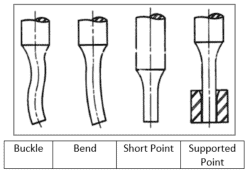
The most critical relationship is “point length to point size”. The punch point must be shaped and sized to satisfy the work piece hole requirement. The length of point required is equal to the sum of the following:
- Length of blend radius;
- Sharpening allowance;
- Length of stripper lip or straight portion in the support bushing;
- Work piece Thickness; and,
- Penetration into Die Cavity.
Excessive sharpening allowances increase the unsupported length which can lead to breakage issues.
Various cross-sectional areas may be used throughout the punch length in order to reduce applied stress levels and improve component performance. Both rigidity and punching load distribution improve as shank diameter increases relative to the punch point size.
Perforating Technology
The perforating punch is an essential yet fragile part of the die assembly. The success of a perforating punch is largely dependent on two key criteria: Physical inter-changeability; and, Structural soundness. When it comes to punch performance, other key criteria include: Strength; Load distribution; Fatigue resistance.
The success of a perforating punch is largely dependent on two key criteria:
- Physical inter-changeability; and
- Structural soundness.
Regarding punch performance, other key characteristics include:
- Strength;
- Load distribution; and,
- Fatigue-resistance.
Structural soundness is impacted by material and construction details.
Perforating punch functionality is largely dictated by two factors:
- The perforating process; and,
- The magnitude of developed loads.
The perforating process requires two actions: 1) Perforating; and, 2) Stripping.
Each action generates different loading conditions. The two actions must be successfully opposed for optimum component performance.
The die button provides a hardened cutting edge to facilitate slug separation.
The die button hole (or cavity) accepts the slug.
The die button hole shape conforms to the punch point; however, the hole is larger to provide for the necessary clearance.
Below the wear land, the die button hole is enlarged to permit unrestricted slug travel.
Die button relief holes are divided into two groups:
- Counter-bore; and,
- Taper relief.
It is important to note that the selected relief hole type to be used is generally determined by individual preference.
The construction type is referred to as stepped when the hole is larger at the intersection with the bottom of the wear land. The balance of the relief hole may be tapered or straight and may not conform with the shape of the die cavity.
No-step construction requires that there be no step at the intersection with the wear land and that the relief hole be tapered to conform with the die cavity shape.
Both construction types are available in headless or headed types. The headless die button must be press- fitted for retention. Headed die buttons may be slip-fitted to avoid distortion of the retainer plate when large numbers must be inserted. The larger bearing surface provided by the head also results in better load distribution.
The perforating process requires two actions:
- Perforating; and,
- Stripping.
Each action generates different loading conditions.
The two actions must be successfully opposed for optimum component performance.
Under impact, a punch is forced through a work piece resulting in the separation of a slug; afterwards, the slug passes through the mating die cavity. The work piece hole conforms to the size and shape of the punch point. Similarly, the slug conforms to the die cavity.
After the hole and slug have been produced, the direction of punch travel is reversed so that it withdraws from the work piece. A stripping mechanism is often used to restrain the work piece during punch withdrawal.
Punch durability is largely dependent upon induced stress levels (relative to the ultimate strength of the component material).
Due to the nature of applied loads, breakage generally occurs during the perforating process; whereas, most cutting-edge wear develops during stripping.
For perforating punches, head breakage is a serious concern. Often times, this concern can be mitigated by increasing the shank diameter so that the load is distributed over a larger area, thereby reducing the stress value.
Improved punch durability can sometimes be achieved by a blend radius that reduces stress concentration in critical areas. For example, cutting edge chipping can be reduced or eliminated by stoning a .002” to .004” radius or chamfer on the component. This procedure effectively increases the contact area resulting in a lower stress level.
The perforating process subjects punch components to a variety of forces, including the following: compressive tensile forces; frictional forces; and, deflecting forces.
Frictional force is equal to the stripping load and directly related to the rate at which the component cutting edges erode. Factors impacting the magnitude of frictional force and, consequently, wear rate are expressed in the following formula:
- F = uN where F = Force of Friction (lbs.)
- u = Coefficient of Friction, and N = Normal Force (lbs.)
Normal Force
If a work piece hole becomes smaller than the perforating punch, it is likely that an interference fit developed during the perforating cycle. The resulting force is known as the “normal force” because its line of action is perpendicular to the direction of the punch travel.
Variables which effect the amount of interference and the magnitude of the normal force include the following:
- Punch-to-die clearance allowances;
- Ratio of hole size to work piece thickness;
- Proximity of the hole to an adjacent part edge;
- Spacing between adjacent holes;
- Type of stripping device utilized; and,
- Cutting edge condition of the perforating components.
For example, clearance allowances must be predicated on the functional requirements of a work piece hole. Small allowances result in minimum roll-over, long burnished lands, and slight angular breaks in the punched holes. In this instance, punch wear is accelerated and slug-jamming problems may develop.
Whereas, large clearances produce more roll-over, shorter burnished lands, and an increase in the break or fracture angle. In this case, the punch wear rate is reduced, but there is a tendency for the slugs to be lifted out of the die cavity. When utilizing larger clearance allowances, slug-ejector punches should be used to prevent slug-pulling.
Punch to die alignment is an expression of the degree of clearance uniformity between corresponding points on the cutting periphery between a punch and die button.
The equation is relatively straightforward: better alignment equals more uniform stamping; and, more uniform stamping equals greater production quantities (by a given die assembly).
Non-uniform clearances subject a punch to unbalanced loads. Unbalanced loads result in deflection, which ultimately leads to premature component failure.
To ensure punch to die alignment during the die construction assembly phase, special attention should be given to the following factors:
- Component of concentricity limits;
- Effect of shape deviations on clearance uniformity;
- Axial relationships in multi-hole retainer plates;
- Effect of the retention system on axial relationships; and,
- Total effect of the combined factors.
Ejector punch components incorporate a spring-loaded pin that extend beyond the face of the punch.
At impact, the pin retracts until it is flush with the punch face. When the slug is separated from the workpiece, the pin exerts a force on the slug to drive it downward or to hold it in position depending upon the punch-to-die clearance allowance.
As the punch is withdrawn, the ejector pin functions like a spring-loaded stripper and prevents the slug from rising with the punch.’
In many instances, a slug-ejector punch is inter-changeable with a solid punch.
A pilot punch must enter a previously punched-hole, contact the hole edge, move the workpiece to its required position, and hold it in place before other components strike the workpiece. The pilot punch is usually .001” smaller on the diameter than its related perforator and has approximately .090” of full diameter lead beyond the face of the perforators. The end of a pilot punch may range from a bullet-nose to conical shape.